Directional Drilling, Start to Finish: Tying the Whole Series Together” — with the full glossary table, the Directional Driller vs. MWD Operator breakdown, rotating vs. sliding explained plainly, and the end-to-end well construction sequence diagram linking back to all 11 prior posts. Saved to outputs.
Full 12-post series recap:
| # | Title |
|---|---|
| 1 | Directional Drilling 1: Understanding Well Profiles |
| 2 | How Directional Drillers Actually Know Where the Drill Bit Is |
| 3 | The Math Directional Drillers Still Do By Hand |
| 4 | Steering the Well: PDMs and Steerable BHAs |
| 5 | Choosing the Right Bit for Directional Drilling |
| 6 | When Things Go Wrong: Stuck Pipe and Drilling Jars |
| 7 | Anti-Collision: Keeping Wellbores From Meeting Underground |
| 8 | Drilling Fluids and Hydraulics |
| 9 | Drill String Connections and Torque |
| 10 | Bottom Hole Assembly Design |
| 11 | Geology Fundamentals |
| 12 | Series Wrap-Up: Start to Finish |
Directional Drilling, Start to Finish: Tying the Whole Series Together
Eleven posts ago, this series started with a simple question: why isn’t a well just a straight line down? Since then we’ve covered well profiles, survey tools, hand calculations, motors, bits, stuck pipe, anti-collision, fluids, connections, BHA design, and the geology that justifies all of it. This final post pulls everything into one place — a working glossary, a plain-language explanation of who does what on the rig, and a start-to-finish walkthrough of how a directional well actually comes together.
The Directional Driller vs. the MWD Operator
Two roles come up constantly throughout this series, and it’s worth being precise about the difference between them, because they’re easy to conflate from the outside.
The Directional Driller is the person responsible for actually steering the well — making the call on toolface, deciding when to slide versus rotate, tracking the slide sheet, and ultimately owning whether the wellbore lands on target. They need working knowledge of survey math, BHA behavior, motor mechanics, and the well plan itself.
The MWD Operator owns the survey tool — assembling it, monitoring its signal while drilling, decoding and delivering surveys to the directional driller, and maintaining the tool between runs. Many MWD operators also process the gamma ray log for the geologist on site. The two roles work in constant communication: the MWD operator provides the data, and the directional driller turns that data into a steering decision.
Rotating vs. Sliding, Explained Plainly
This distinction from post 4 is worth restating clearly, because it’s genuinely one of the most important concepts in the entire series.
- Sliding means the drill string itself isn’t rotating — only the mud motor’s rotor is turning, driven by fluid flow, spinning just the bit. Because the bent housing’s orientation stays fixed while sliding, this is how a directional driller actively steers: whatever direction the toolface is pointed, that’s the direction (and the build/drop) the well moves in.
- Rotating means the entire drill string is turning, motor included. In rotating mode, the bent housing’s effect on direction essentially averages out in every direction around the wellbore, so the well tends to drill straighter — this is the mode used for making faster progress once the desired trajectory is already achieved, or through the “tangent section” described back in post 1.
Every directional well is really a sequence of decisions about when to slide (steer) and when to rotate (drill ahead), and that decision loop runs continuously from kickoff to total depth.
The Complete Glossary
Pulling together the core vocabulary that’s been used across this entire series:
| Term | Meaning |
|---|---|
| KOP | Kickoff Point — the depth where controlled deviation from vertical begins |
| Inclination | The wellbore’s angle from vertical, measured via gravity |
| Azimuth | The wellbore’s compass direction, measured via magnetic or gyroscopic reference |
| BUR / DOR | Build-Up Rate / Drop-Off Rate — how fast inclination changes, in degrees per 30m |
| DLS | Dogleg Severity — total combined curvature (inclination + azimuth change) per 30m |
| TVD / MD | True Vertical Depth (straight-down depth) vs. Measured Depth (actual wellbore length) |
| Toolface | The direction the bend in the motor is pointing, referenced to either gravity (GTF) or magnetic north (MTF) |
| Slide Sheet | The hand-updated table directional drillers use to track position and project ahead between surveys |
| Separation Factor | The go/no-go anti-collision number comparing offset distance against combined survey uncertainty |
| PDM | Positive Displacement Motor — the mud-powered steering tool at the heart of most modern directional BHAs |
How a Directional Well Actually Gets Drilled
Zooming all the way out, here’s the sequence this entire series has effectively walked through, one post at a time:
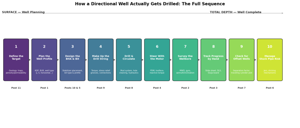
It starts with geology. Before anything else, the target has to be defined — a trap, a reservoir zone, a specific point in specific rock (post 11). Everything downstream exists to reach that point.
Then comes the plan. The target and its displacement from surface get translated into a well profile — vertical, J-type, S-type, horizontal, or double-build — with a chosen KOP and build rate (post 1).
The hardware gets selected. The BHA is designed around the profile’s stabilizer needs (post 10), and a bit is chosen to match the formation and the dogleg the plan requires (post 5).
The string gets built. Every connection in that string is made up to the correct torque, with the right lubrication and inspection discipline, because directional wells put more fatigue stress on threads than a straight hole ever would (post 9).
Drilling begins, with a fluid system engineered to clean the hole, control pressure, and — on MWD wells — carry survey data to surface (post 8).
Steering happens continuously, alternating between sliding (using the motor’s bent housing to actively build, drop, or turn) and rotating (drilling ahead once the desired trajectory is achieved) (post 4).
Position gets confirmed regularly through survey tools — MWD in real time, gyro where magnetic interference is a concern (post 2) — and tracked by hand on the slide sheet between surveys, using BUR and dogleg severity math to stay ahead of the next decision (post 3).
Nearby wells get checked continuously, especially on multi-well pads, using separation factor calculations and traveling cylinder plots to make sure this wellbore never gets dangerously close to another one (post 7).
And the whole time, the crew is managing risk — watching for the sticking mechanisms that could trap the string, with jars in the BHA ready as a last resort if something does go wrong (post 6).
That sequence repeats, survey after survey, connection after connection, until the wellbore reaches its target — at which point everything this series has covered has done its job.
Why This Series Exists
Directional drilling sits at an unusual intersection of physics, geology, mechanical engineering, and old-fashioned hands-on judgment. None of the individual pieces covered in this series are impossibly complicated on their own — but they only make real sense together, which is exactly why this was worth doing as a series rather than one overwhelming post. If you’ve followed along from post 1, you now have a genuinely solid working picture of how a directional well gets planned, drilled, and landed on target — not just the vocabulary, but the reasoning behind it.
That’s the series. Thanks for reading through it start to finish.
This is post 12, the final post in a series on the fundamentals of directional drilling. The full series: well profiles (1), survey tools (2), BUR/dogleg severity math (3), steerable motors (4), bit selection (5), stuck pipe/jars (6), anti-collision (7), drilling fluids (8), connections/torque (9), BHA design (10), and geology fundamentals (11).