Bottom Hole Assembly Design: How Stabilizer Placement Steers a Well Without a Motor
Post 4 in this series covered how a steerable PDM bends a wellbore using an adjustable bent housing. But motors haven’t always been the default, and even today, plenty of directional work still gets done with a rotary assembly — no bent housing, no adjustable anything, just drill collars and stabilizers arranged in a specific order. This post covers how that works, because the underlying physics (side force and drill collar stiffness) is worth understanding even on wells that do use a motor.
The Core Idea: Side Force
Every rotary BHA design comes down to one concept: side force — the sideways force applied at the bit that pushes it toward, or away from, the low side of the hole. Generate enough side force in the right direction, and the bit deviates predictably; balance it out, and the well holds its current angle instead.
Side force isn’t generated by anything electronic or hydraulic in a rotary assembly — it comes purely from where stabilizers are placed along the BHA relative to the bit, combined with how much the drill collars between them are allowed to flex under weight on bit. Get the stabilizer spacing right, and gravity and mechanics do the steering work for you.
Stiffness: The Other Half of the Equation
Stabilizer placement alone doesn’t tell the whole story — the stiffness of the drill collars between stabilizers matters just as much. A stiffer collar resists bending under weight on bit, which changes how much of that weight actually translates into side force at the bit versus just being absorbed by the collar’s own rigidity. This is why BHA design isn’t just “put a stabilizer here” — it’s a genuine balance between collar stiffness, stabilizer spacing, and the weight being applied while drilling.
The Basic Assembly Types
Slick Assembly
No stabilizers at all — just the bit and drill collars. Without anything constraining the string’s position in the hole, a slick assembly tends to behave unpredictably and isn’t typically used when directional control actually matters. It’s mentioned mostly as the baseline everything else improves on.
Single-Stabilizer BHAs
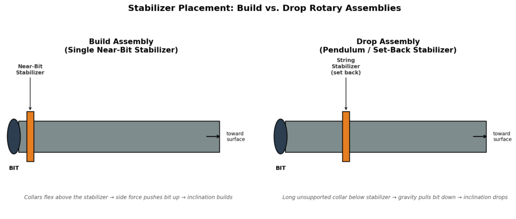
One stabilizer, placed at a specific distance from the bit, is enough to create a meaningful steering tendency — either build or drop, depending entirely on where that single stabilizer sits.
- Near the bit — this creates what’s often called a fulcrum effect. The stabilizer acts as a pivot point, and the unsupported collar above it flexes under weight on bit, pushing the bit toward the high side of the hole and building inclination.
- Set back from the bit — this leans on the pendulum effect instead. With the stabilizer positioned further up the string, a longer unsupported section of collar hangs below it, and gravity pulls that section — and the bit with it — toward vertical, dropping inclination.
Two-Stabilizer BHAs
Adding a second stabilizer gives more control over the assembly’s overall stiffness and tendency, letting drillers fine-tune between a stronger build tendency, a neutral (angle-holding) tendency, or a controlled drop, depending on exactly how far apart the two stabilizers are placed and how much unsupported collar sits between and below them.
Multi-Stabilizer BHAs
More than two stabilizers creates a stiffer, more packed assembly overall — generally used when the goal is to hold inclination steady and resist unwanted deviation, rather than actively build or drop. The extra wall contact makes the whole assembly behave more like a rigid rod than a flexible one, which naturally resists the bit wandering off the current trajectory.
How Stabilizer Position Changes Side Force
The relationship between stabilizer distance from the bit and the resulting side force isn’t linear — it’s most dramatic close to the bit, tapers off in the middle range, and then a different effect (the pendulum length increasing) starts to dominate again further up the string.
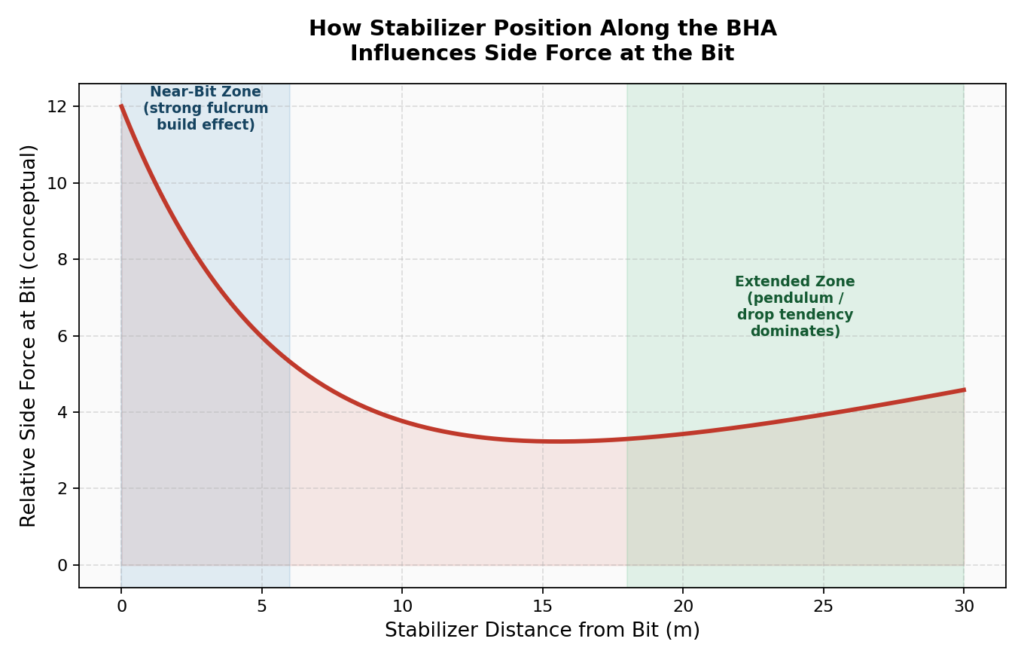
This is exactly why “near-bit” stabilizers get such specific attention in BHA design — small changes in position close to the bit have an outsized effect on build tendency, while stabilizers positioned further back are working through a fundamentally different mechanism (pendulum weight) rather than the fulcrum effect.
Matching the BHA to the Job
| Goal | Typical Approach |
|---|---|
| Building inclination | Near-bit stabilizer, fulcrum effect, often with a specific unsupported collar length above it tuned to the build rate needed |
| Holding inclination | Two or more stabilizers spaced to balance fulcrum and pendulum tendencies against each other, or a more packed multi-stabilizer configuration |
| Dropping inclination | Stabilizer set back from the bit, pendulum effect, relying on an unsupported collar section and gravity to pull the bit back toward vertical |
None of these configurations are set-and-forget, either — formation hardness changes the amount of side force that actually translates into real deviation, so the same BHA on paper can behave differently in different rock, which is exactly why field experience in a specific area still counts for a lot even with the math worked out in advance.
Why This Still Matters in a Motor-Driven World
It’s tempting to think rotary BHA theory is a relic now that steerable motors dominate directional drilling — but the same fulcrum and pendulum principles are still at work in every BHA, motor or not. A steerable motor’s bent housing adds an extra, adjustable source of side force on top of whatever the rest of the BHA’s stabilizer placement is already contributing. Understanding rotary assembly theory is really understanding the baseline physics that every directional BHA, motorized or not, is built on top of.
Coming Up Next
We’ve now covered planning, surveying, math, motors, bits, stuck pipe, anti-collision, fluids, connections, and BHA design. The next post steps back from the mechanics entirely and covers the geology side — the reservoir traps, rock types, and wellbore stability basics that actually decide where a directional well needs to go, and why, in the first place.
This is post 10 in an ongoing series on the fundamentals of directional drilling. Catch up on well profiles (post 1), survey tools (post 2), BUR/dogleg severity math (post 3), steerable motors (post 4), bit selection (post 5), stuck pipe/jars (post 6), anti-collision (post 7), drilling fluids (post 8), and connections/torque (post 9) if you’re just joining in.