If you’ve ever seen a diagram of an oil well, there’s a good chance it wasn’t a straight vertical line. Modern wells curve, bend, go sideways, and sometimes even curve back toward vertical before they’re done. None of that happens by accident — it’s the result of a discipline called directional drilling, and the “shape” a well takes is called its well profile.
In this first post of the series, I want to break down exactly what a well profile is, why there are different types, and how directional drillers decide which one to use. This is foundational stuff — if you understand well profiles, the rest of directional drilling (surveys, BHAs, motors, all of it) starts to make a lot more sense.
What Is Directional Drilling, Really?
At its simplest, directional drilling is the practice of intentionally steering a wellbore away from vertical so that it reaches a target that isn’t directly below the drilling rig. That target might be:
- An oil or gas reservoir located under a lake, a town, or a protected area where you can’t put a rig directly overhead
- A thin, horizontal reservoir layer that you want to intersect along its length instead of just punching through it vertically
- A relief well drilled to intercept a blowout
- Multiple reservoirs accessed from one surface pad, to save space and cost
Directional drilling isn’t new — the first controlled directional well was successfully used to kill a blowout back in 1934 — but the tools and precision available today are a different world entirely.
The Five Basic Well Profiles
Every well plan starts with choosing a profile. There are five that come up again and again in the field:
1. Straight (Vertical) Well
This is the baseline case — the well stays at (or very close to) 0° inclination from top to bottom. It’s the simplest profile and the one every other profile is compared against.
2. Slant Well (J-Type)
A J-type well starts vertical, then builds angle at a chosen Kickoff Point (KOP) until it reaches a target inclination, and then holds that angle in a straight “tangent section” all the way to the target. Picture the letter J, tipped on its side — that’s exactly why it’s named that.
3. S-Type Well
An S-type well does everything a J-type does — builds to an angle and holds it — but then it drops the angle back down again, usually returning close to vertical before reaching total depth. This is useful when the target itself needs to be approached at a shallower angle, or when there’s a reason to straighten the wellbore again lower down.
4. Horizontal Well
This one builds all the way from vertical to a full 90° inclination — literally sideways. Horizontal wells became hugely important once operators realized how much more reservoir contact you get by drilling along a thin, flat formation instead of just punching through it. This is a big part of what made shale plays commercially viable.
5. Double-Build Horizontal Well
A more complex version of the horizontal profile: the well builds to an intermediate angle, holds for a while, and then builds a second time up to 90°. This gives planners more control over exactly where the well enters the horizontal section relative to the target zone.
Here’s what all four non-vertical profiles look like next to each other, plotted as horizontal displacement against true vertical depth (TVD):

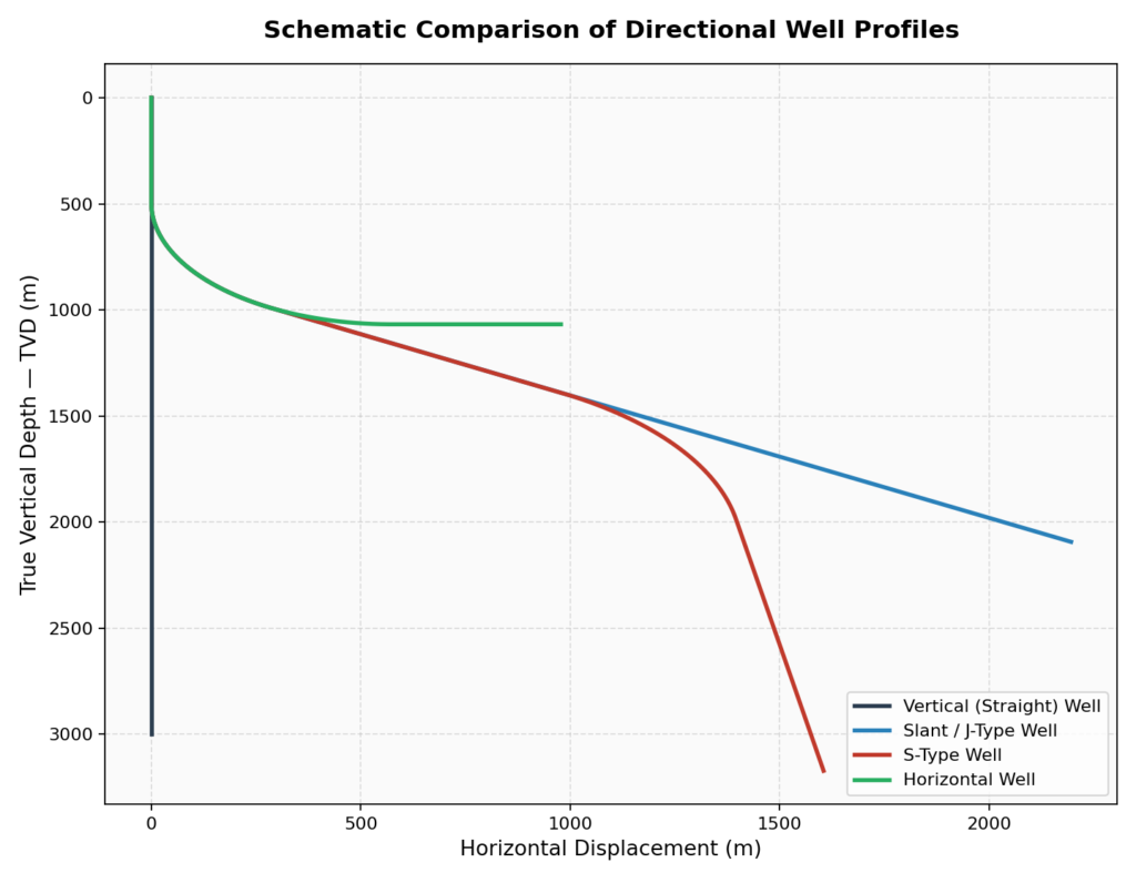
Note: these are simplified schematic paths, not an actual well plan — the real values (kickoff depth, build rate, hold length) get customized to the specific target on every single well.
The Vocabulary You Need to Know
Before any of this makes sense on paper, you need a handful of terms that show up in literally every well plan:
| Term | What It Means |
|---|---|
| KOP (Kickoff Point) | The depth where controlled deviation from vertical begins |
| Inclination | The angle of the wellbore from vertical, measured against gravity |
| Azimuth | The compass direction of the wellbore, measured against a northern reference |
| BUR (Build-Up Rate) | How fast inclination increases, expressed in degrees per 30 metres |
| DOR (Drop-Off Rate) | How fast inclination decreases, again in degrees per 30 metres |
| TVD (True Vertical Depth) | The straight-down depth from surface to any point in the well |
| MD (Measured Depth) | The actual length of the wellbore drilled, following the curve |
| EOB (End of Buildup) | The point where the controlled increase in inclination stops |
Once you have BUR and KOP, you can actually calculate the radius of the curve the well is going to follow, using a surprisingly simple relationship:
Radius (m) = 1718.89 ÷ BUR (°/30m)
That constant, 1718.89, shows up again and again in directional drilling math — it falls straight out of converting an arc length formula into a “degrees per 30 metres” convention.
Not All Curves Are Created Equal: Radius Classification
Once you know the radius of a build section, wells get grouped into three categories:

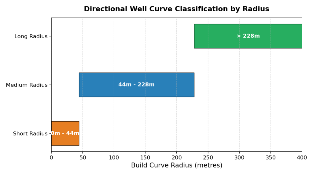
- Short radius — under 44 metres. These are tight, aggressive curves, generally used for very specific applications like re-entries from an existing wellbore.
- Medium radius — between 44 and 228 metres. This is the most common range for standard build-and-hold or horizontal wells.
- Long radius — greater than 228 metres. Gentler curves, often used when the tools or casing design can’t tolerate a tighter bend, or when the target is far enough away that a gradual build works fine.
The tighter the radius, the more mechanical stress everything in the drill string experiences going around that curve — which is exactly why the choice of radius isn’t arbitrary. It flows directly into decisions about bottom hole assembly design, motor bend settings, and even which type of drill bit will hold up best.
Why the Profile Choice Actually Matters
It’s tempting to think of the well profile as just a geometry exercise, but it drives real decisions:
- Equipment selection — a horizontal well needs a very different bottom hole assembly than a simple slant well.
- Cost — tighter curves and more complex profiles generally cost more to plan, survey, and execute.
- Risk — every degree of curvature adds torque and drag on the drill string, and increases the chance of problems like differential sticking or a stuck pipe.
- Reservoir contact — for a thin, flat formation, a horizontal profile can expose far more producing rock to the wellbore than a vertical one ever could.
A good well plan balances all of this: it hits the target, respects the restraints the client has set (maximum dogleg, boundary lines, etc.), and does it as cheaply and safely as the geology allows.
Wrapping Up
Well profiles are the starting point for every directional drilling project — before a directional driller ever talks about survey tools, mud motors, or bit selection, someone has already decided: is this well going to be a slant, an S-type, or a full horizontal? That decision shapes everything downstream.
In the next post, we’ll go a level deeper and look at how directional drillers actually know where the drill bit is once it’s thousands of metres underground and completely out of sight — the surveying tools and methods (MWD, gyroscopes, magnetometers) that make all of this possible in the first place.
This post is part of an ongoing series breaking down the fundamentals of directional drilling in plain language. If you found this useful, the next post covers how survey tools actually locate the drill bit downhole.