Anti-Collision: Keeping Wellbores From Meeting Underground
Every post so far in this series has treated each well as if it exists in isolation — plan it, survey it, steer it, done. In reality, most wells don’t get drilled alone. Multi-well platforms, tightly packed pad drilling, sidetracks off old wellbores, and relief wells drilled specifically to intercept a blowout all share one requirement: knowing, with confidence, exactly how close a new wellbore is getting to every other wellbore nearby. That’s the job of anti-collision analysis, and it’s one of the more mathematically interesting parts of well planning.
Why This Isn’t Optional
Think about a modern multi-well pad — a dozen or more wells kicking off from surface locations just a few metres apart, all fanning out toward different targets. Or an offshore platform with dozens of slots packed into a small footprint. In both cases, wellbores that start close together often stay close together for a significant stretch of their path, especially near the top of the curve. If a new well’s actual position, survey error and all, could plausibly overlap with an existing wellbore, drilling ahead without checking that first is a serious risk — hitting an old wellbore isn’t just an inconvenience, it can mean a blowout, a collision with production tubing, or the loss of an entire well.
This is exactly why anti-collision isn’t a one-time check — it’s an ongoing scan performed throughout well planning and while actively drilling.
The Ellipsoid of Uncertainty (EOU)
Here’s the core problem anti-collision math has to deal with: no survey is perfect. Every survey tool — MWD, gyro, whatever — has some margin of error in its measurement of inclination and azimuth, and that error compounds as you go deeper. A tiny azimuth error near the surface barely matters, but the same tiny error, projected out over three kilometres of measured depth, can translate into a real, physically significant positional uncertainty.
To manage this mathematically, each survey point isn’t treated as a single, certain location — it’s treated as the center of a three-dimensional zone of possible actual positions, called the Ellipsoid of Uncertainty. The tool error models behind this take into account the specific survey instrument’s known error characteristics (gyro vs. magnetic MWD vs. single shot) and grow that ellipsoid larger the deeper the well goes.
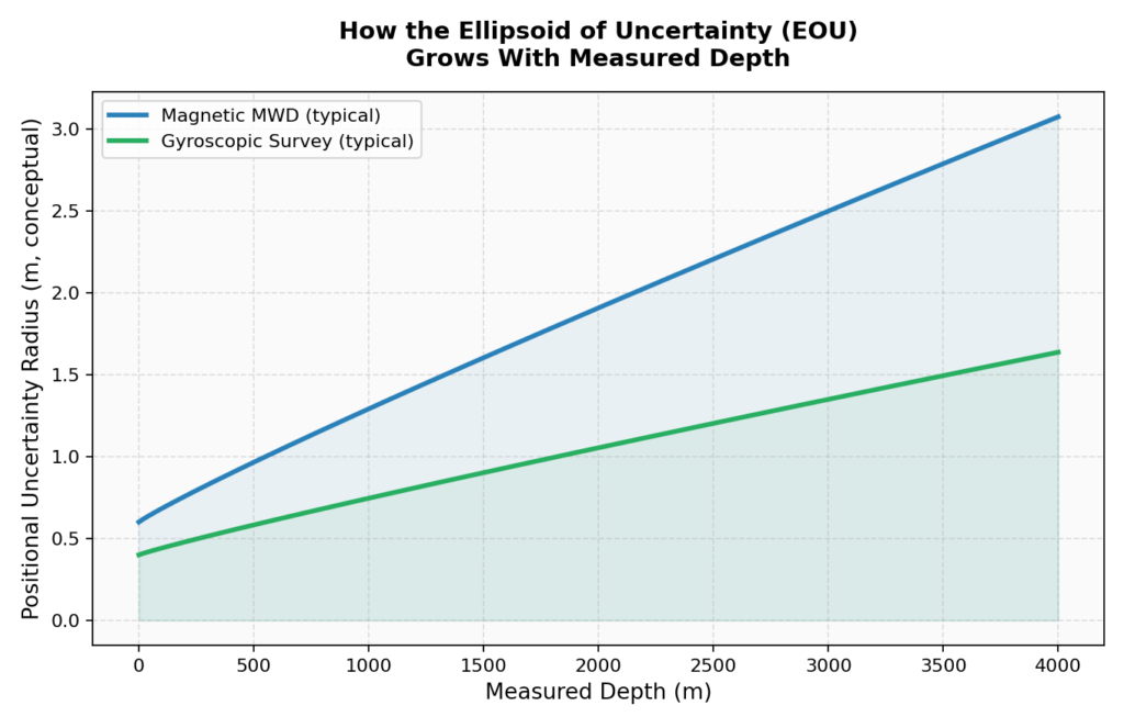
This is also exactly why gyroscopic surveys matter so much on anti-collision-sensitive wells — since they aren’t affected by magnetic interference from nearby casing or other wellbores, their uncertainty grows more slowly, which keeps the ellipsoid smaller and the collision math more forgiving at depth.
Separation Factor: The Go/No-Go Number
Once you have an ellipsoid of uncertainty around your planned well and a similar ellipsoid around every nearby offset well, anti-collision analysis boils the comparison down to a single practical number: the Separation Factor.
At a basic level, the Separation Factor compares the actual center-to-center distance between two wellbores against the combined radius of their two uncertainty ellipsoids at that point. A Separation Factor greater than 1 means the ellipsoids don’t overlap — the wells are considered safely separated, even accounting for survey error. As that number drops toward 1 and below, the risk of an actual collision, even if neither well is exactly where its survey says it is, increases sharply.
This single number is what allows a well design to be objectively signed off, audited, and re-checked every time survey data updates — instead of relying on someone eyeballing a plot and hoping for the best.
Reading a Traveling Cylinder Plot
The Separation Factor is the number planners rely on, but the Traveling Cylinder Plot is how anti-collision risk gets visualized for a human to actually look at. Picture the reference wellbore collapsed down to a single point at the center of a plot, viewed end-on — like looking straight down the axis of a cylinder. Every nearby offset well’s position, at the corresponding depth, gets plotted relative to that center point, using high side and right of highside as the two axes instead of standard north/east coordinates.
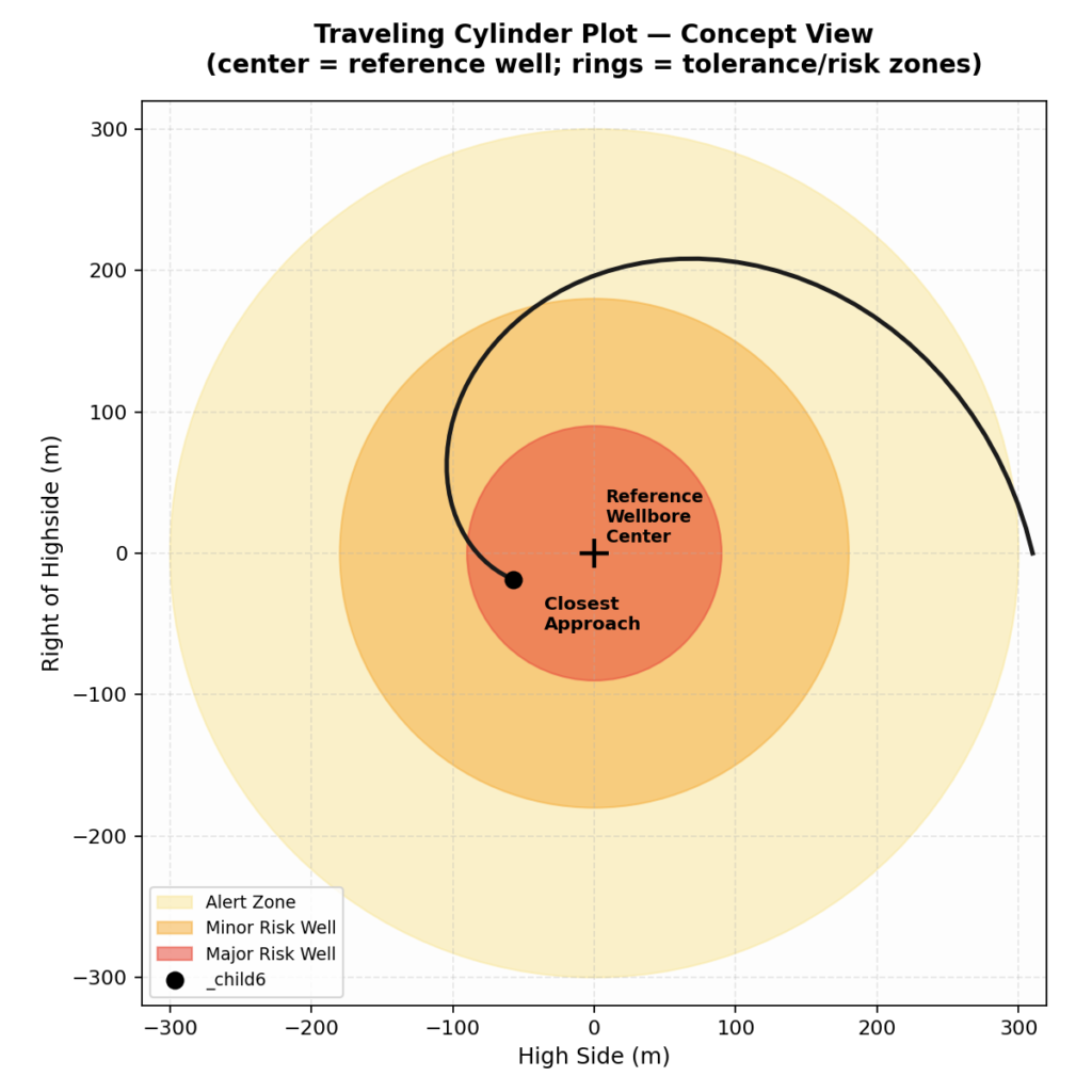
Around that center point, tolerance lines are drawn — rings representing the risk thresholds discussed below. As the well is drilled, the offset well’s position on this plot is updated survey by survey, and directional hands can see at a glance whether an approaching offset well is safely out in the green, drifting into a caution zone, or closing in on the reference wellbore itself.
The Risk Classification System
Standard anti-collision procedures generally define escalating risk categories based on how close that Separation Factor gets:
| Classification | What It Means | Typical Response |
|---|---|---|
| Alert Zone | Offset well is within a defined proximity distance, worth tracking | Increased monitoring, no operational restriction yet |
| Minor Risk Well | Separation factor has dropped into a range that warrants active management | Tighter survey frequency, review of well path if needed |
| Major Risk Well | Separation factor is low enough that a collision is a real possibility | Requires explicit review, possible re-plan, or approval before continuing |
This tiered system exists so that engineering attention scales with actual risk — most offset wells never leave the “alert” stage, but the ones that do get real scrutiny before drilling continues past them.
Why Sidetracks Get Special Treatment
Sidetracks deserve a specific mention here, because they create a subtlety anti-collision scanning has to handle carefully: a sidetracked wellbore shares its upper section with the original hole, then diverges. Scanning has to correctly treat the shared section as identical (not two separate risks) while still properly evaluating the new, diverged section against every other nearby well — otherwise you either get false alarms on the shared section or miss real risk on the new one.
The Bigger Picture
Anti-collision isn’t a single calculation done once during well planning — it’s baked into survey program design (how often you survey and with what tool), execution monitoring (checking scan reports as new surveys come in), and even influences early decisions like well spacing on a pad. Get it right, and multiple wells can be packed safely and efficiently into a small footprint. Get it wrong, and the consequences are some of the most serious in the entire industry.
Coming Up Next
We’ve now covered planning, surveying, hand calculations, motors, bits, stuck pipe, and how wells avoid each other underground. The next post moves into the fluid side of the operation — drilling fluids and hydraulics basics: what mud actually needs to do downhole, the main fluid types, and why something as simple as viscosity has such an outsized effect on a directional well.
This is post 7 in an ongoing series on the fundamentals of directional drilling. Catch up on well profiles (post 1), survey tools (post 2), BUR/dogleg severity math (post 3), steerable motors (post 4), bit selection (post 5), and stuck pipe/jars (post 6) if you’re just joining in.