Drilling Fluids and Hydraulics: Why “Just Mud” Is Doing More Than You Think
It’s easy to think of drilling mud as a supporting character — something that gets pumped down the hole so cuttings come back up, and not much else. In directional drilling, that mental model breaks down fast. The fluid isn’t just carrying cuttings; it’s controlling pressure, cooling the bit and motor, transmitting MWD data to surface, and — especially once a well starts building toward horizontal — actively determining whether the hole even stays clean enough to keep drilling at all.
This post covers the fluid fundamentals every directional hand needs, and why they get noticeably more important the further a well leans away from vertical.
What Drilling Fluid Actually Has to Do
Strip away the chemistry and a drilling fluid has a short list of core jobs to perform simultaneously:
- Hole cleaning — carry drilled cuttings up out of the wellbore and to surface
- Pressure control — maintain enough hydrostatic pressure to hold back formation fluids, without exceeding the fracture pressure of the rock
- Lubrication and cooling — reduce friction and heat at the bit and any downhole motor
- Cuttings suspension — keep solids suspended when circulation stops, instead of letting them settle back down onto the bit and BHA
- Formation support — help seal permeable formations with a filter cake, and minimize damage to the producing zone
- Hydraulic energy transmission — deliver enough hydraulic horsepower to the bit and, in a PDM well, to the motor itself
- Signal transmission — in MWD wells, actually carry the survey and logging data back to surface
Every one of these functions competes for the same limited set of fluid properties, which is exactly why fluid engineering is its own specialty rather than an afterthought.
The Three Main Fluid Families
Water-Based Fluids
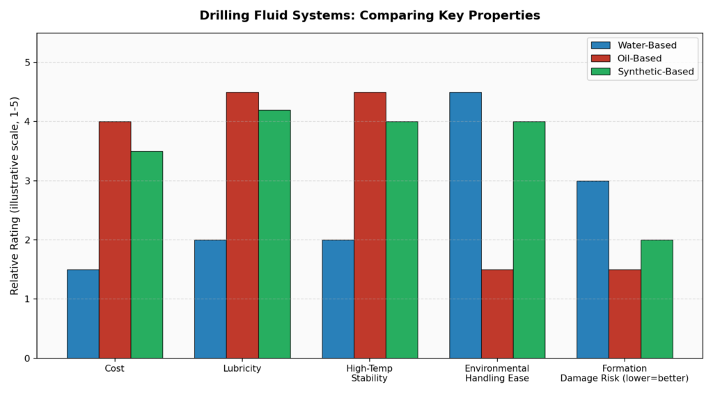
The default starting point for most wells — water as the continuous phase, with clays and additives controlling viscosity, filtration, and other properties. They’re the cheapest option and the easiest to handle environmentally, but they generally offer less lubricity and are more prone to reacting with certain shale formations, causing swelling or instability.
Oil-Based Fluids
Here, oil is the continuous phase instead of water, typically with a small percentage of water emulsified into the system. Oil-based muds offer excellent lubricity (a real advantage in high-friction directional and horizontal sections), strong high-temperature stability, and much better shale inhibition. The tradeoffs are real, though: higher cost, and far more complicated environmental handling and disposal requirements.
Synthetic-Based Fluids
A middle path — synthetic base fluids engineered to deliver oil-based-like performance (lubricity, thermal stability) while being more environmentally manageable than true oil-based systems. They cost more than water-based muds but are often the practical choice for offshore and environmentally sensitive extended-reach wells where oil-based discharge simply isn’t an option.
Rheology: The Property That Decides Whether Cuttings Actually Come Out
“Rheology” sounds academic, but it boils down to a very practical question: how does this fluid actually flow, and how much resistance does it have to being deformed? Three specific rheological values get watched closely on every well:
- Plastic Viscosity (PV) — resistance to flow caused by the concentration, size, and type of solids in the fluid. High PV generally means more friction pressure while circulating.
- Yield Point (YP) — the resistance to the fluid starting to move; essentially how much force is needed before flow even begins. Higher yield point improves the fluid’s ability to lift and carry cuttings.
- Gel Strength — how much the fluid thickens up once it’s sitting still. This determines how well cuttings stay suspended the moment circulation stops, like during a connection.
These three numbers aren’t independent — they’re a genuine three-way balancing act. Push viscosity and yield point too high, and you get excessive pump pressure, more strain on the mud motor, and higher equivalent circulating density downhole. Too low, and cuttings stop being carried efficiently, especially once the well isn’t vertical anymore.
Why This Gets Harder as the Well Leans Over
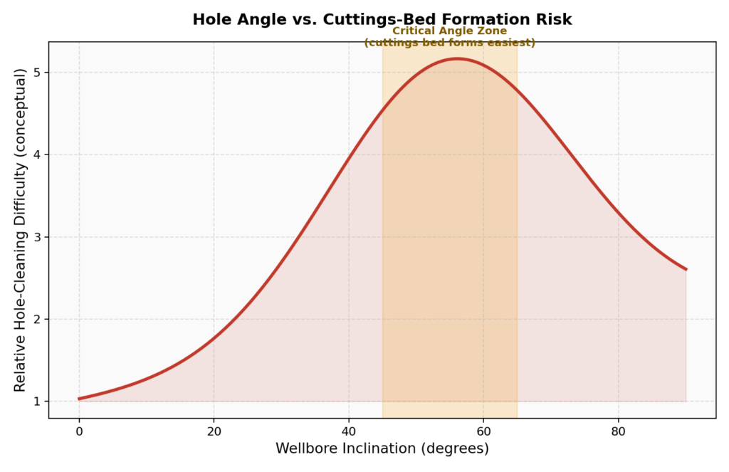
In a vertical well, gravity is doing you a favor — cuttings that fall out of suspension just fall straight back down through the flow path, and get picked back up. Once a well starts building angle, that stops being true. Cuttings that fall out of suspension land on the low side of the hole instead, and if the fluid isn’t managing it well, they build up into a cuttings bed — a genuinely dangerous accumulation that increases torque and drag, raises the risk of a stuck pipe, and can seriously compromise hole cleaning efficiency.
There’s a specific angle range where this problem is at its worst — well before full horizontal. In the roughly 45°-65° range, cuttings are heavy enough that low-side settling happens easily, but the wellbore isn’t yet at an angle where the whole cross-section rotates fast enough to keep sweeping them along. This is often referred to informally as the critical angle zone, and it’s exactly where hole cleaning problems concentrate most.
This is exactly why high-angle and horizontal sections often call for higher annular velocities, specific rheological profiles (favoring a strong yield point and reasonable gel strength), pipe rotation whenever possible, and closer monitoring of returns at the shakers — all standard practice for extended-reach and horizontal wells, but far less critical in a straightforward vertical hole.
The Fluid’s Second Job: Talking to the Surface
For any well running MWD, the drilling fluid has one more job that has nothing to do with cuttings at all — it’s the medium that carries survey and logging data to surface, most commonly through mud pulse telemetry. A positive pulse tool restricts mud flow momentarily to create a small pressure spike; a negative pulse tool briefly vents mud out to the annulus to create a pressure drop. Either way, the signal has to travel all the way up the drill string through the fluid column to be decoded at surface.
That means fluid properties directly affect telemetry reliability. Excessive gas content, heavy solids loading, or poor overall fluid condition can all degrade the pulse signal on its way up, making the data harder to decode — one more reason fluid quality control isn’t optional on an MWD-equipped directional well.
Bringing It Together
None of these fluid properties exist in isolation from everything else covered in this series — the same mud has to satisfy hole cleaning at whatever inclination the well plan calls for, protect the formation, lubricate the motor and bit from post 4 and post 5, and keep the MWD signal from post 2 readable at surface, all at the same time. Fluid engineering on a directional well is really an exercise in managing tradeoffs across every other system this series has covered.
Coming Up Next
We’ve now covered planning, surveying, math, motors, bits, stuck pipe, anti-collision, and fluids. The next post looks at the metal itself — drill string connections and torque: why thread design matters so much more in a curved wellbore, stress relief grooves, and how make-up torque actually gets calculated on the rig floor.
This is post 8 in an ongoing series on the fundamentals of directional drilling. Catch up on well profiles (post 1), survey tools (post 2), BUR/dogleg severity math (post 3), steerable motors (post 4), bit selection (post 5), stuck pipe/jars (post 6), and anti-collision (post 7) if you’re just joining in.