So far in this series we’ve covered how a well is planned (post 1), how directional drillers know where the bit is (post 2), and the math used to track progress between surveys (post 3). Now for the part that actually does the steering: the Positive Displacement Motor, or PDM — better known on the rig floor as a mud motor.
A steerable PDM is the single most common way directional wells get drilled today. It’s a purely mechanical, hydraulically-powered tool with no electronics involved in the steering itself — which is honestly part of why it’s so reliable. Understanding how it works also explains a lot of the terminology that shows up constantly in directional drilling conversations: toolface, reactive torque, stalling, bend setting.
The Four Sections of a PDM
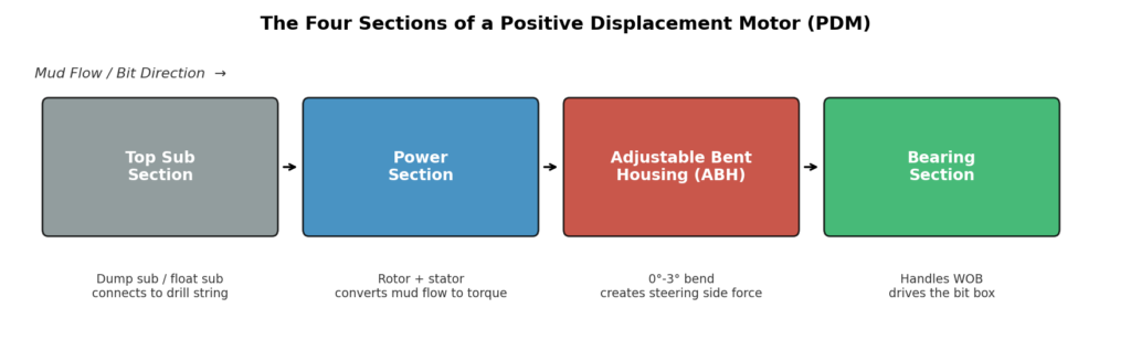
A PDM breaks down into four distinct sections, stacked end to end, each doing a specific job on the way from the drill string down to the bit:
1. Top Sub Section
This is the connection point to the rest of the drill string above. It usually takes the form of a dump sub — a sub with ports that open to let mud drain out of the drill string when tripping out of the hole, and let it fill back up when tripping in. Without this, you’d be pulling a drill string full of heavy mud out of the hole every single trip, which is both slow and unnecessary. In underbalanced drilling situations, a plugged top sub is used instead, to stop the well and drill string from communicating when the pumps are off.
2. Power Section
This is where the actual conversion happens — hydraulic force from the flowing mud becomes mechanical rotary torque. It’s built from two key parts:
- The rotor — a spiraled steel rod, chrome-coated, that runs the length of the section.
- The stator — a rubber (elastomer) sleeve with one more “lobe” than the rotor, fitted tightly around it.
As mud is pumped through, it’s forced between the rotor and stator, and that pressure differential is what makes the rotor spin inside the stator. This is the part of the motor that determines both how fast the bit turns and how much torque it produces — which brings us to the lobe/stage tradeoff.
3. Adjustable Bent Housing (ABH)
This is the section that actually makes the well curve. It allows a small, deliberate bend — typically adjustable in a range from 0° to 3° — between the power section and the bearing section below it. That bend is what points the bit slightly off-axis and generates the side force that pushes into the formation and steers the well.
4. Bearing Section
The bearing section handles the weight applied to the bit while drilling (WOB) and transmits torque down to the bit box, all while allowing continuous rotation under that load. There are two main designs — mud lube bearings, which use a small diverted flow of drilling fluid for lubrication, and sealed bearings, which run in a self-contained oil chamber and don’t need that back pressure at all.
Lobes and Stages: The Core Design Tradeoff
Every PDM rotor/stator pair is described by two numbers: lobe count and stage count, and both matter a lot for how the motor actually performs downhole.
- More lobes = less speed, more torque. A simple 1-lobe rotor spins fast but doesn’t generate much torque. A 7 or 9-lobe rotor spins much more slowly but produces far more torque — useful for larger bits or harder formations.
- More stages = more torque. A “stage” is one complete spiral turn of a lobe along the rotor’s length. Stack more stages, and you get more torque out of the same motor, independent of the lobe count.
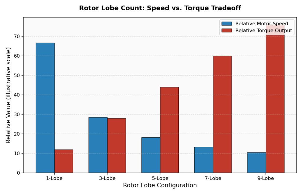
This is exactly why there’s no single “best” motor — the right rotor/stator combination depends entirely on the bit type, formation hardness, and hole size for that specific well. Manufacturers test every motor configuration on a dyno machine, mapping out speed, torque, and horsepower against flow rate and weight on bit, so drillers can pick the right one from a handbook rather than guessing.
Reactive Torque: The Steering Side Effect Nobody Can Skip
Here’s something that trips up a lot of people new to directional drilling: when the bit turns to the right while taking weight, the drill string above it twists to the left in reaction. This is reactive torque, and it’s simple Newtonian physics — action and reaction — but it has a very real, practical consequence for steering.
When a directional hand orients the motor’s toolface off bottom (before touching down and drilling), the string is essentially untwisted. The moment weight is applied and the bit starts drilling, reactive torque winds the string slightly, and the toolface actually seen on bottom shifts away from where it was set off bottom. A driller has to anticipate this and deliberately offset the off-bottom toolface to compensate — for example, setting up 75° off bottom, knowing 30° of reactive torque will bring it down to the intended 45° once weight goes on.
Get this wrong, and the well simply doesn’t go where it was supposed to — which is exactly why reactive torque gets so much attention in directional drilling training.
What Actually Causes a Motor to Stall
A motor stall happens when there’s more resistance from the formation than the motor can overcome — the bit simply stops rotating even though mud is still being pumped. You’ll see it immediately on the surface as a spike in pump pressure, because the mud has nowhere productive to go and is forcing its way past the rotor and stator instead of turning them properly.
Stalls aren’t just an inconvenience — repeated stalling accelerates wear on the stator and can cause premature motor failure. There’s also a specific right way to recover from one: never pull off bottom with the pumps still running at full rate. A stall winds up trapped torque in the assembly, and if that torque releases suddenly while pulling off bottom, it can spin violently in reverse — occasionally hard enough to back a connection off downhole entirely, turning a stall into a fishing job. The safe move is to reduce pump rate to roughly half speed before pulling off bottom, letting the trapped torque bleed off gradually instead of all at once.
Why the PDM Became the Default Choice
Rotary assemblies, whipstocks, and jetting all still have their place, but the steerable PDM won out as the standard tool for one simple reason: it gives a directional driller direct, adjustable control over both build rate and direction, without needing to trip out and change hardware every time the plan shifts slightly. The bend setting can be adjusted at surface, the motor can drill in either sliding mode (steering actively, off the bend) or rotating mode (drilling straighter, with the whole string turning), and it does all of this with a purely mechanical design that’s proven itself over decades of use.
Coming Up Next
We’ve now covered planning, surveying, hand calculations, and the tool that steers the well — the next post turns to the other end of the drill string: how drill bits are actually selected for directional work, why gauge row design and cutter size matter so much more here than in straight-hole drilling, and the difference between roller cone and PDC bits when it comes to holding a toolface.
This is post 4 in an ongoing series on the fundamentals of directional drilling. Catch up on well profiles (post 1), survey tools (post 2), and BUR/dogleg severity math (post 3) if you’re just joining in.