Geology Fundamentals Every Directional Driller Should Know
Ten posts into this series and we still haven’t answered the most basic question of all: why does any of this — the curves, the surveys, the motors, the bit selection — actually matter? The answer is geology. Every directional well exists to reach a specific target in the ground, and that target is defined entirely by where hydrocarbons happen to be trapped. This post steps back from the mechanics and covers the geological basics that quietly justify every engineering decision in the previous ten posts.
Where Hydrocarbons Actually Come From, Briefly
Oil and gas form deep underground from organic material buried and subjected to heat and pressure over long geological timescales. Once formed, they don’t just sit still — being less dense than the surrounding water, they migrate upward through permeable rock until something stops them. That “something” is called a trap, and understanding the two main trap types explains why wells end up shaped the way they do.
Structural Traps vs. Stratigraphic Traps
Structural Traps
A structural trap forms when the Earth’s crust physically deforms — folding or faulting rock layers into a shape that catches rising hydrocarbons. The classic example is an anticline: layers of rock folded upward into an arch, with a non-porous cap rock sealing the top. Hydrocarbons rise through the porous reservoir rock underneath and collect at the crest of the fold, exactly where gravity and buoyancy naturally push them, with gas on top, oil below it, and water underneath that.
Stratigraphic Traps
A stratigraphic trap doesn’t rely on folding at all — instead, it forms where the reservoir rock itself changes character laterally, often thinning out and disappearing (“pinching out”) into non-porous rock. Hydrocarbons trapped this way accumulate right at the edge where the porous layer runs out, sealed in place not by a fold but by the rock simply stopping being permeable.
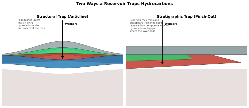
This distinction matters directly for well planning: a structural trap target is usually a fairly well-defined high point that a well plan can aim at with reasonable confidence, while a stratigraphic trap target often has a much less predictable boundary — which is exactly the kind of situation where the target size and displacement math covered back in post 1 becomes critical to get right.
Reservoir Rock, In Plain Terms
Two properties decide whether a rock formation is worth drilling at all:
- Porosity — how much empty space exists within the rock, expressed as a percentage of the total rock volume. This is essentially the storage capacity for hydrocarbons.
- Permeability — how well those pore spaces are actually connected to each other, which determines whether fluid can flow through the rock at all. A rock can have excellent porosity and still be nearly worthless as a reservoir if its permeability is too low for hydrocarbons to move through it toward a wellbore.
A useful way to think about it: porosity is the size of the tank, permeability is the size of the pipe leading out of it. Both matter, and a directional well aims to intersect rock that scores well on both counts — which is a big part of why horizontal wells became so valuable in tight, low-permeability shale formations, since drilling along the reservoir instead of straight through it dramatically increases the contact area available for hydrocarbons to reach the wellbore.
Rock Mechanics: What Drilling a Hole Actually Does to the Rock Around It
Before a well is drilled, the rock at any given depth sits in a natural state of stress, generally in equilibrium in every direction. The moment a hole is drilled, that equilibrium is broken — rock that used to be there is gone, and the surrounding rock has to redistribute the stress that rock used to carry. This redistribution is the root cause of nearly every wellbore stability problem in the industry: if the redistributed stress exceeds what the surrounding rock can handle, you get breakout (rock failing and spalling into the hole), or in the opposite direction, fracturing.
Why Deviated Wells Face a Different Stability Challenge Than Vertical Ones
Here’s the part that connects directly back to everything else in this series. In a vertical well, the stress redistribution around the borehole is roughly symmetric — the same in every direction around the hole, which makes it comparatively easier to predict and manage with a well-chosen mud weight (from post 8).
Once a well starts building inclination, that symmetry breaks down. The stress field around a deviated wellbore becomes directional — different on the high side versus the low side, and different again depending on which way the well is heading relative to the natural stress orientation of the rock. That’s exactly why extended-reach and horizontal wells are generally more prone to wellbore instability than an equivalent vertical well drilled through the same formation.
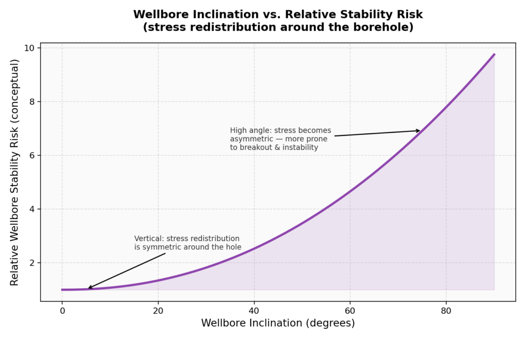
This is also precisely why so much of what’s been covered earlier in this series scales in importance as wells get more deviated: hole cleaning and mud weight management from post 8, dogleg severity limits from post 3, and even bit selection from post 5 — an overly aggressive bit chewing unevenly into an already stressed formation is a real contributor to hole problems in high-angle sections.
How Formation Type Feeds Back Into Everything Else
Geology isn’t a standalone topic in directional drilling — it’s the input that every other decision in this series responds to:
| Earlier Post | How Formation Geology Drives the Decision |
|---|---|
| Post 5 — Bit Selection | Formation hardness and abrasiveness decide roller cone vs. PDC, cutter size, and blade count |
| Post 8 — Drilling Fluids | Shale reactivity, formation pressure, and permeability drive fluid type and mud weight selection |
| Post 3 — BUR / Dogleg Severity | Rock competence and stability limits how aggressive a build section can safely be |
| Post 6 — Stuck Pipe | Permeable, overpressured, or reactive formations directly cause differential sticking and hole instability |
| Post 1 — Well Profiles | Trap type and target size shape which well profile (horizontal, S-type, etc.) actually makes sense |
None of these earlier posts’ decisions are made in a vacuum — they’re all downstream of the geology a specific well is drilling through.
Bringing the Series Full Circle
It’s fitting that geology comes near the end of this series rather than the start, because it’s genuinely easier to appreciate once you understand what the well plan, the survey tools, the motor, the bit, and the fluid are all actually trying to accomplish. Every tool and technique covered in this series exists to serve one goal: reaching a specific point in a specific rock formation, safely and predictably. Geology is the “why” behind all of it.
Coming Up Next
This has been a long series, and the final post ties it all together — a start-to-finish walkthrough of how a directional well actually gets drilled, recapping the key terms and roles (Directional Driller vs. MWD Operator, rotating vs. sliding), and linking back through all eleven previous posts.
This is post 11 in an ongoing series on the fundamentals of directional drilling. Catch up on well profiles (post 1), survey tools (post 2), BUR/dogleg severity math (post 3), steerable motors (post 4), bit selection (post 5), stuck pipe/jars (post 6), anti-collision (post 7), drilling fluids (post 8), connections/torque (post 9), and BHA design (post 10) if you’re just joining in.