Drill String Connections and Torque: The Small Details That Hold a Directional Well Together
Nine posts into this series, we’ve covered the well plan, the survey tools, the motor, the bit, the fluid — everything that makes a directional well steerable. This post covers something less exciting but no less critical: the connections that hold the drill string together. In a directional well specifically, threads take a beating that a straight vertical hole simply never puts them through, and understanding why is genuinely useful, not just trivia.
Why Threads Are the Weakest Link, Structurally Speaking
Every drill string component gets subjected to torsional stress (from rotation), tensile stress (from its own hanging weight), and collapse pressure. But threads specifically are singled out as the biggest concern, for a simple reason grounded in basic mechanical engineering: any point where a component’s dimensions change abruptly is a stress concentrator — and a thread, by definition, is nothing but a repeating sequence of abrupt angle changes cut into metal.
In a straight vertical well, this is manageable. In a directional well, it gets worse, because the drill string is also being bent every time it goes around a curve. That bending loads one side of every connection with extra resistive force, and as the string rotates, that stress transfers around the face of the connection in the direction of rotation — creating additional fatigue stress that a vertical well’s connections never have to deal with at all. This is exactly why connection design gets so much more attention on directional jobs.
The Connection Types You’ll Actually Encounter
Numbered Connections (NC)
Introduced by the API in 1968, NC connections became the industry standard because they’re continuously updated with stress-relief features that older designs lack. When people talk about IF, FH, or XH connections today, they’re very often still cutting an NC-spec thread — the old names just stuck around out of habit even after the underlying thread standard changed.
The Obsolete Names That Still Get Used
- IF (Internal Flush)
- FH (Full Hole)
- XH (Extra Hole)
These were the original thread families the NC standard replaced. They lacked the stress-relief grooves that NC threads now include as standard, which is why they were formally made obsolete — but you’ll still hear the names on location, since old habits (and old paperwork) don’t disappear overnight.
Regular Connections (REG)
Regular connections use more threads per inch than NC connections of the same size, with shallower thread depth as a result. That gives them strong torsional strength but weaker tensile strength in smaller sizes — which is exactly why REG connections are reserved for drill bits and larger tubulars (7¾” and up), where tensile strength matters less.
Hughes Connections (H90)
A distinctive design using a 90° thread angle instead of the 60° angle used everywhere else. Like REG connections, H90 offers good torsional strength but weaker tensile strength, limiting its use to BHA applications where the string won’t be carrying heavy tensile loads.
Stress Relief Grooves and the Bore-Back Modification
Since the sharp root of a standard thread is exactly the stress concentrator problem described above, the fix is mechanically simple: cut a small, rounded groove into the base of the connection instead of leaving a sharp thread root. That rounded profile spreads load across a wider area instead of concentrating it at one sharp point.
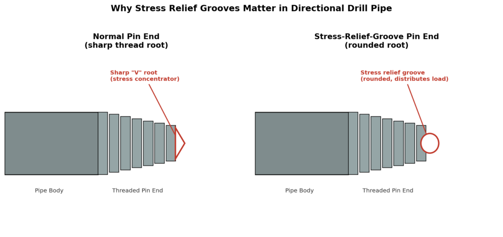
Both the pin end (grooved at the base, starting from the last thread) and the box end get this treatment. On the box end specifically, a later refinement called the bore-back modification proved to be an even better stress-relief geometry than the original curved-groove design, and it’s now common on modern connections.
Make-Up Torque: How Tight Is Tight Enough?
Make-up torque is the amount of rotational force used to actually tighten a connection together, and it’s tied directly to the torsional yield strength of that connection and its metal grade. The industry works off two standard reference points:
New pipe: make-up torque = 50% of torsional yield
Used pipe: make-up torque = 60% of torsional yield
The logic behind going higher on used pipe is straightforward — a connection that’s already seen wear benefits from a bit more binding force to resist working loose downhole. But there’s a real tradeoff hiding here too: tightening a connection well past the minimum make-up torque steadily reduces its remaining tensile strength, so “tighter is always better” isn’t actually true. Operators generally aim to set make-up torque above the highest torque they expect the connection to see downhole — because a connection that tightens itself further while drilling is a real problem, risking a belled and weakened box end.
Turning Torque Into Something You Can Actually Apply: Tong Length and Line Pull
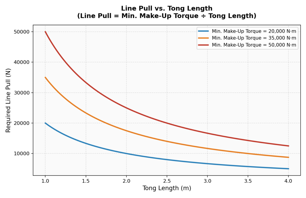
On the rig floor, torque isn’t dialed in directly — it’s applied through tongs, using a load cell and line pull gauge. The relationship is simple leverage:
Line Pull = Minimum Make-Up Torque ÷ Tong Length
Longer tongs mean less line pull is needed to hit the same torque target — exactly like using a longer wrench. This relationship needs to be recalculated for every different tong length in use, and it’s also affected by the angle the tong line makes with the cathead chain — ideally 90°, since any other angle reduces the actual torque the connection experiences relative to what the gauge reads.
The Checklist: Making Up a Connection the Right Way
A few specific practices come up again and again as non-negotiable steps for connection life:
| Step | Why It Matters |
|---|---|
| First-time connections get special treatment | A newly machined thread has microscopic burrs that peel off on first contact — the first make-up should only go to 50% of minimum torque, then be broken, cleaned, re-lubricated, and made up properly |
| Clean and inspect every break | Visual inspection at minimum on every connection broken out; a full non-destructive testing pass at least every 1,500 circulating hours |
| Lubricate correctly and evenly | Drill collar dope typically needs 40-60% powdered metallic zinc by weight; drill pipe dope uses lead oxide instead — applied across the entire connection, including the seal face |
| Check tong length and angle before torquing | Both directly change what torque the connection actually experiences relative to the gauge reading |
| Rotate the break point | On trips in and out of the hole, the joint being made up or broken should be rotated periodically to spread wear evenly and avoid fatiguing the same connection repeatedly |
Skipping any of these doesn’t usually cause an immediate failure — it shows up later, as a connection that fails earlier than it should have, often at the worst possible time.
Why This Deserves Its Own Post
It would be easy to file connections under “just hardware,” but every other system in this series depends on the string actually holding together under directional loading — the motor in post 4, the bit in post 5, even the jars in post 6 all rely on connections that won’t twist off or wash out mid-run. Thread design is quiet, unglamorous engineering, but it’s exactly the kind of detail that separates a well that finishes clean from one that turns into a fishing job.
Coming Up Next
The next post moves into bottom hole assembly design more broadly — how stabilizer placement, drill collar stiffness, and the physics of side force let a rotary assembly build, hold, or drop inclination without a steerable motor at all.
This is post 9 in an ongoing series on the fundamentals of directional drilling. Catch up on well profiles (post 1), survey tools (post 2), BUR/dogleg severity math (post 3), steerable motors (post 4), bit selection (post 5), stuck pipe/jars (post 6), anti-collision (post 7), and drilling fluids (post 8) if you’re just joining in.