The drill bit gets less glamour than the motor sitting above it, but it’s arguably just as important to a directional well. A great motor with the wrong bit underneath it still won’t hold a toolface, still won’t build angle predictably, and still might wander off the planned trajectory no matter how good the well plan is. This post covers how bit selection actually shapes directional performance — starting with the biggest fork in the road: roller cone or PDC.
The Two Bit Families
Roller Cone Bits
Roller cone bits drill by crushing and gouging the formation with rotating cones. There are two subtypes: insert bits, with carbide inserts cemented into the cones, and mill tooth bits, where the cutting structure is milled directly out of the cone metal. Because they have moving parts riding on bearings, their working life is limited by bearing wear as much as by cutting structure wear — and running them at high RPM (like behind a fast mud motor) wears the bearings out faster than the cutters. For that reason, only roller cone bits with sealed friction bearings are recommended for directional work.
PDC Bits (Fixed Cutter)
PDC — polycrystalline diamond compact — bits have no moving parts at all. They drill by shearing the rock rather than crushing it, which is generally more efficient and gentler on the borehole. Since there’s nothing to wear out mechanically, bit life comes down to cutter wear and heat management instead. PDC bits have become the dominant choice in directional and horizontal drilling, mostly because their cutter layout can be engineered specifically for steerability in a way a roller cone simply can’t be.
There are also specialty variants — TSP (thermally stable PDC) bits for high-temperature wells, and natural diamond / diamond impregnate bits, reserved for the hardest formations where even PDC cutters would fail quickly.
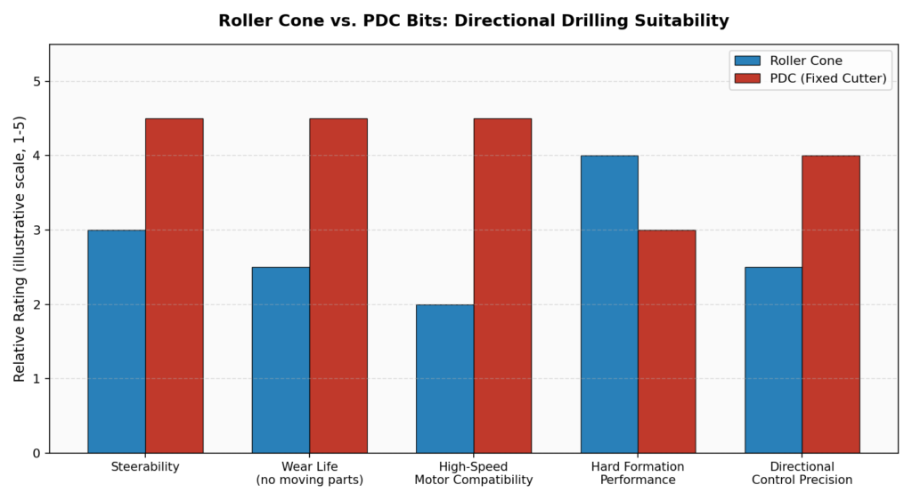
Why Gauge Row Design Decides How Well a Bit Steers
Here’s a detail that’s easy to overlook: it’s not the whole bit that determines directional performance so much as the gauge row — the outermost row of cutters. When a directional BHA applies side force to push the bit into the formation, it’s the gauge row that has to actually cut in response.
- A gauge row with long cutters angled toward the center of the bit resists that side force and steers poorly.
- A gauge row with shorter cutters angled toward the outside of the bit responds to side force and steers well.
Because that same gauge row also takes the brunt of the side-loading stress, gauge protection — usually flush-mounted inserts or hardfacing just below the gauge row — is essential to stop premature wear from ruining the bit’s ability to hold gauge partway through a run.
Cutting Structure Balance: Steerable vs. “Hole Tracking”
A bit with most of its cutters concentrated on the outer row and very few on the inner rows was essentially designed to track the existing hole — great for going straight, bad for directional work, because it actively resists deviation. A bit with a more balanced cutting structure between the outer and inner rows reduces that hole-tracking tendency and gives the directional driller much better control when steering is actually needed.
PDC-Specific Limits for Directional Work
A few PDC design details matter enough that they show up as hard rules of thumb in the field:
| Design Factor | Directional Drilling Guidance |
|---|---|
| Blade count | Fewer than 5 blades is not recommended — low blade count makes reactive torque less constant, which makes it harder to hold a steady toolface |
| Cutter size | Cutters larger than 13mm should generally be avoided — bigger cutters are more aggressive but harder to steer precisely |
| Depth-of-cut control | Secondary “limiter” cutters, set slightly behind the primary cutters, can be used to control how aggressively each blade shears the formation — improving directional predictability |
Bit Profile, Taper, and Core: The Shape That Controls Dogleg
Beyond the cutting structure, the physical shape of a fixed-cutter bit — its profile, taper, and core — has a direct effect on how much dogleg it’s capable of achieving.
- Profile (short, medium, or long, measured from the nose to the outer shoulder cutter) — shorter profiles allow tighter doglegs; longer profiles resist deviation and track straighter.
- Taper — the angle between the nose and shoulder of the bit. A steeper taper reduces achievable dogleg; a shallower one increases it.
- Core — the height difference between the bit’s nose and its center. A deep core helps the bit follow an existing hole faithfully (useful when you don’t want deviation); a flatter core lets the bit wander more freely and supports higher doglegs — which is exactly why flat-core bits are often chosen for sidetracking work.
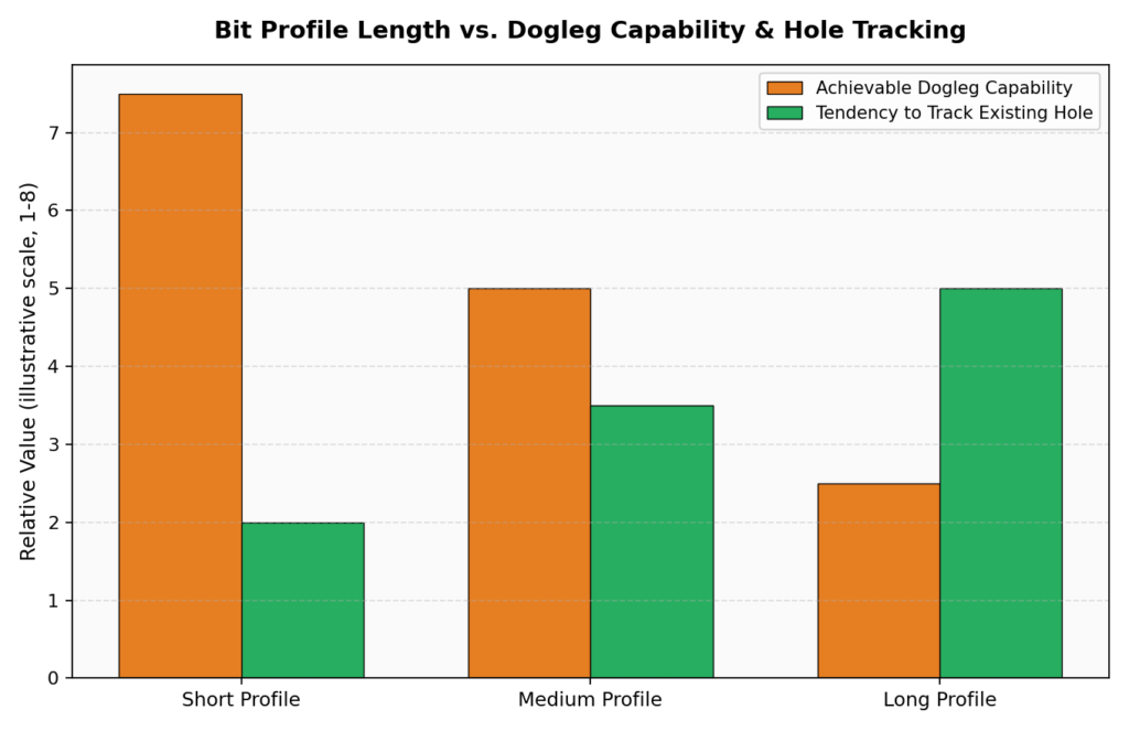
The overall rule of thumb: the shorter and less tapered the bit, the more aggressively it can build angle — but that same aggressiveness makes it more sensitive to formation changes and harder to control precisely, so it’s a genuine tradeoff, not a free win.
IADC Bit Grading: A Shared Language for Wear and Type
Because so many manufacturers make bits, the industry standardized on the IADC code — a simple 3-digit system for roller cone bits that communicates hardness class, hardness subtype, and special features in a way any operator can read regardless of brand. It pairs with a standardized IADC wear grading system, which lets teams compare how a bit actually wore across different runs, different wells, and different manufacturers on a consistent basis — useful both for picking the next bit and for building a track record of what works in a given formation.
Putting It Together
Choosing a directional bit really comes down to matching three things at once: the formation you’re drilling (hardness, abrasiveness), the motor and RPM it’ll be run behind, and the dogleg severity the well plan actually requires. A bit that’s perfect for a long, gentle horizontal lateral might be completely wrong for a tight kickoff curve on the same well — which is exactly why bit selection happens fresh for every BHA run, not just once per well.
Coming Up Next
We’ve now covered planning, surveying, hand calculations, the motor, and the bit — the next post shifts to what happens when things go wrong: stuck pipe and the drilling jars built to get a string moving again, including how cocking and tripping loads are calculated for both mechanical and hydraulic jars.
This is post 5 in an ongoing series on the fundamentals of directional drilling. Catch up on well profiles (post 1), survey tools (post 2), BUR/dogleg severity math (post 3), and steerable motors (post 4) if you’re just joining in.