Understanding MWD Directional Tools: A Simple Guide
Modern drilling operations rely heavily on Measurement While Drilling (MWD) tools to understand where the drill bit is going and what kind of rock it is cutting through. These tools send real‑time data to the surface so drilling teams can make quick and accurate decisions.
In this post, we’ll break down the major components of MWD systems—directional sensors, accelerometers, magnetometers, the Gamma Ray (GR) tool, and transmission systems—using simple language and a clean diagram.
What MWD Directional Tools Do
Every MWD system provides three essential measurements:
- Inclination – how steep the wellbore is.
- Azimuth – the compass direction of the wellbore.
- Tool Face – the orientation of the tool and bit.
To calculate these, MWD tools use one main sensor package.
The MWD Sensor Package
MWD directional sensors are built from:
- 3 orthogonal accelerometers
- 3 orthogonal magnetometers
These six sensors work together to define orientation in three‑dimensional space.
Diagram: Basic MWD Sensor Layout
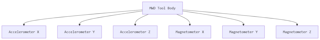
This layout allows the tool to read gravity and magnetic field components along all three axes.
Accelerometers: Measuring Inclination and Tool Face
Accelerometers measure the component of Earth’s gravity along each axis.
They work on the force‑balance principle, meaning they detect how much force gravity applies in a specific direction.
What they help determine:
- Inclination – calculated from the gravity components.
- Tool face – the orientation of the tool around the wellbore axis.
Because the Bottom Hole Assembly (BHA) orientation changes as drilling progresses, each accelerometer reads a different portion of gravity. Combining their readings gives a complete picture of the tool’s tilt.
Magnetometers: Measuring Azimuth
Magnetometers measure the Earth’s magnetic field along their axis.
When a coil is wrapped around a soft iron core and placed in a magnetic field, the induced current changes depending on the coil’s angle. That current change reveals the magnetic direction.
Magnetometers help determine:
- Azimuth – the compass direction of the well path.
- Part of the tool face calculation (when combined with accelerometers).
MWD Gamma Ray (GR) Tool
The Gamma Ray Tool identifies changes in formation lithology.
Key points:
- Gamma rays come mainly from Potassium, Thorium, and Uranium.
- These radioactive elements are more abundant in shales.
- Therefore, GR logs are excellent shale indicators.
- For fastest lithology detection, the GR sensor is placed close to the bit, below the directional sensors.
Transmission and Control Systems
Collecting data is only half the job—MWD tools must also transmit that data to the surface.
How Transmission Works
- The control system collects, stores, and sends measurements.
- There is no electrical switch from the surface.
- The tool activates when it detects a physical change like increased pump pressure.
- Data travels up the well through the mud using mud pulse telemetry, which creates pressure pulses in the drilling fluid.
These pulses are interpreted at the surface to rebuild the measurements.